
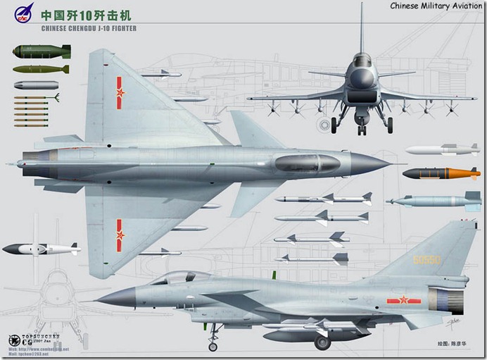
3-view drawing of the Chengdu J-10A with available weapons options.
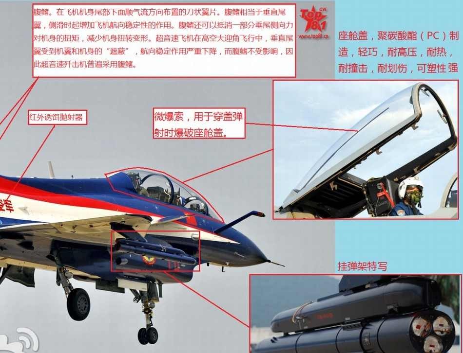
- A J-10SY (a J-10S built or modified especially for the PLAAF August 1st display team) illustrates the
- smoke generator (similar to the PL-9
with the same aerodynamic shape and characteristics).
The twin canopy is also highlighted. The inset details the lightning strike discharger on the J-10A - (single seater)

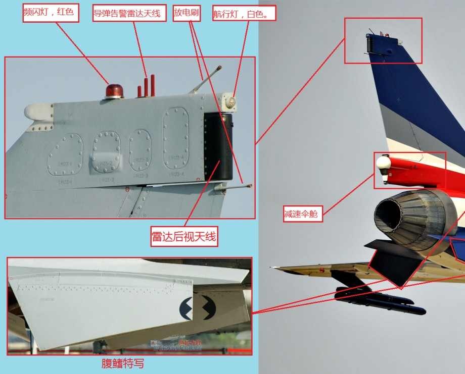
- Upper left corner: detail of the J-10s vertical tail. From front to back. Probably an ECM antenna
- (for front aircraft coverage), a red navigation light, probably “Odd Rods” IFF antenna, a static discharge
- wick, a rear navigation light, a cover over the ARW-9101 RWR and finally another static discharge wick.
- Below a closeup of the ventral fins possible containing aerials for communications equipment. Right:
- (other than what’s already covered) and the parachute housing with ECM transciever below.

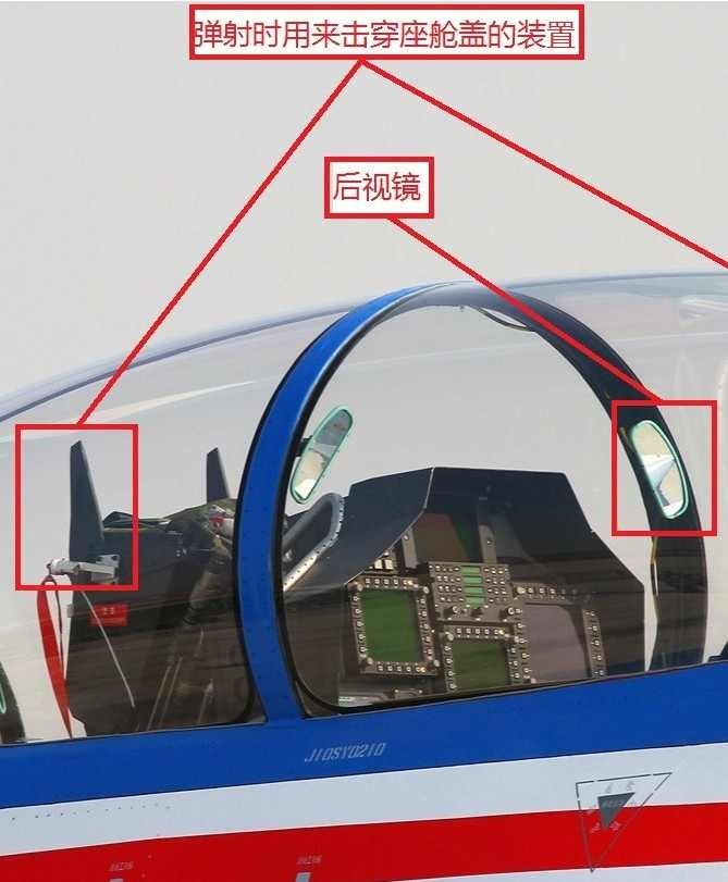
- This photo illustrates the J-10SY’s zero-zero ejection seat’s attitude sensors. Also note the canopy rear view mirrors. The rear cockpit instrument panel contains a HUD repeater (top) and 3 digital color multi-function displays. Note the construction number on the canopy rail.

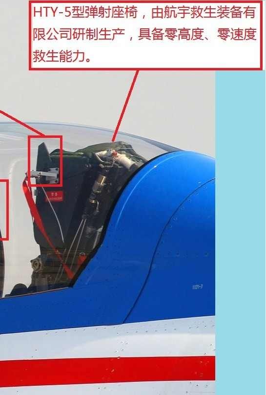
- Close up detail view of the rear cockpit HTY-5 ejection seat attitude sensor.

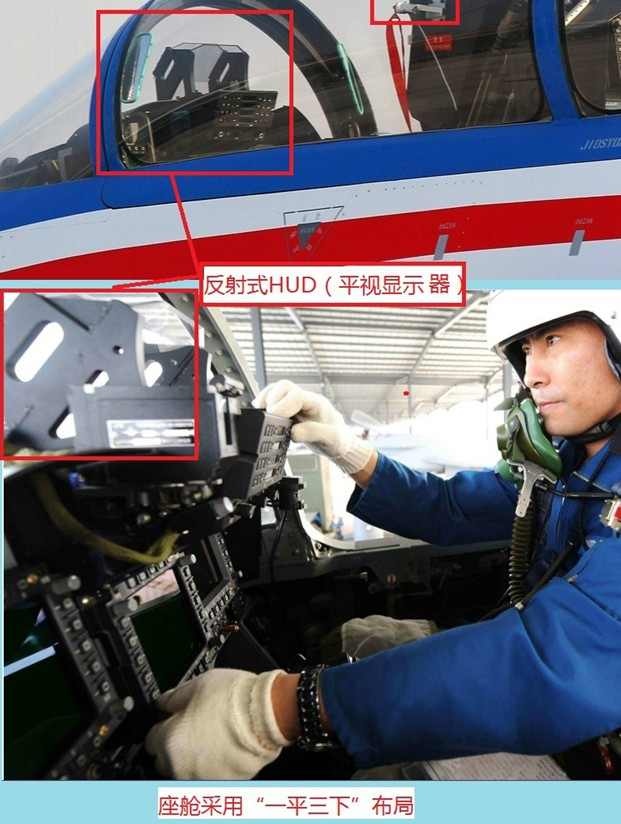
- Front cockpit HUD (control panel below) and the ejection seat attitude sensor. The construction number is available on the canopy rail.

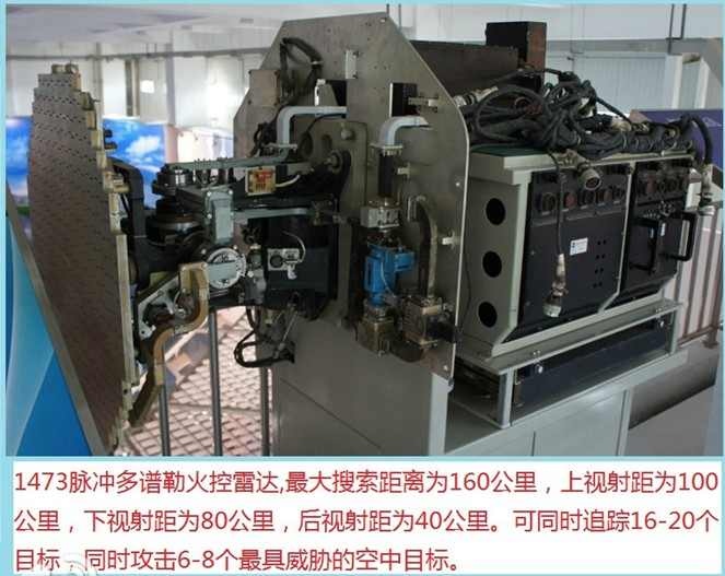
- The KLJ-3 multimode radar. The KLJ-3 is said to be based on the AN/APG-66/88 series. It’s said to have a maximum detection range of 81 miles and an engagement range of 56 miles. It can also track 4 to 6 targets simultaneously and engage 2 targets at one time.

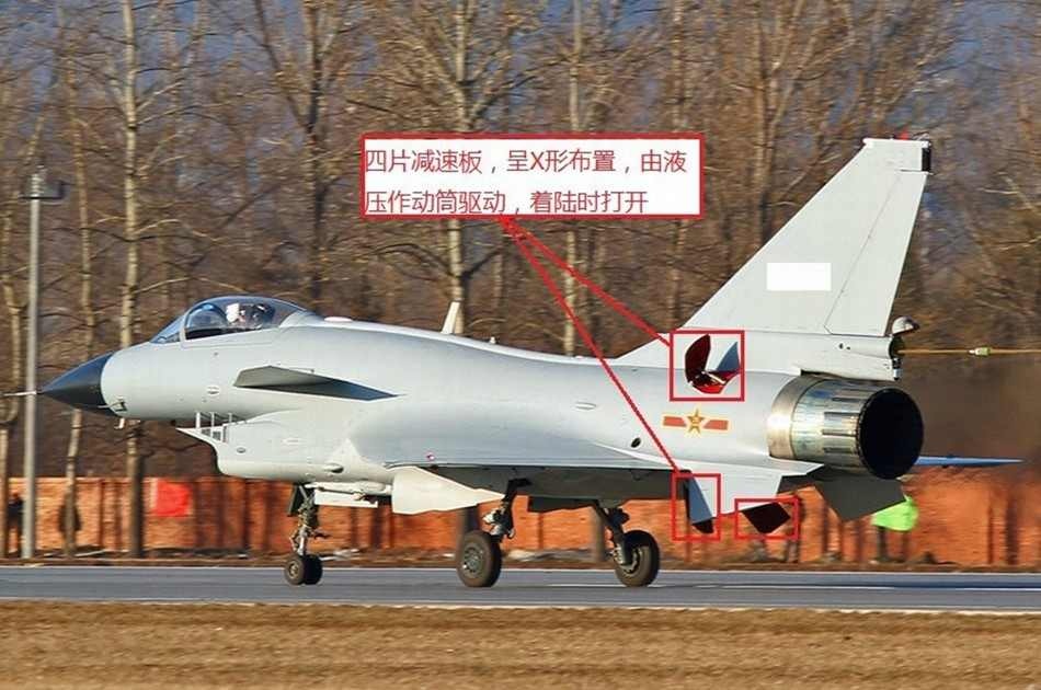
- Tangentially located four-petal airbrakes on the rear fuselage (2 are located next to the tail and the other
- 2 are located between the ventral stabilators.

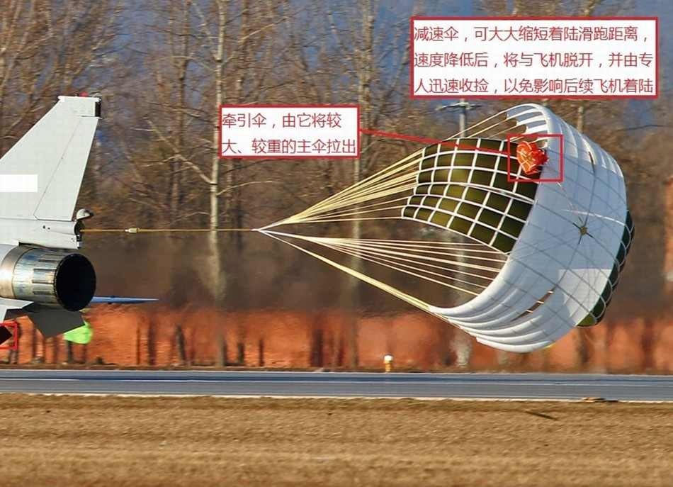
- The J-10’s cruciform braking parachute as deployed on landing.


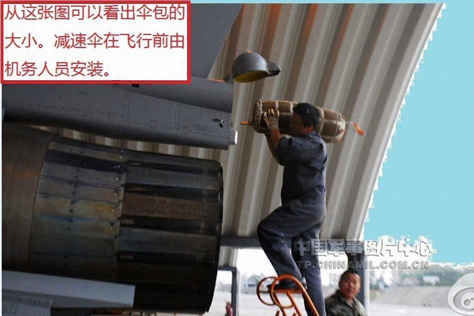
- The J-10’s braking parachute being installed in it’s storage compartment on the aircraft.
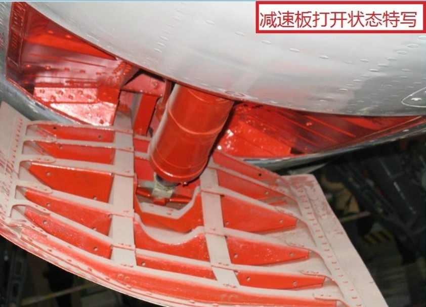
- A closeup the interior of one of the J-10’s ventral airbrakes. Interiors of airbrakes and bays are painted
- red as they are on US Navy aircraft to alert groundcrew of deployment.

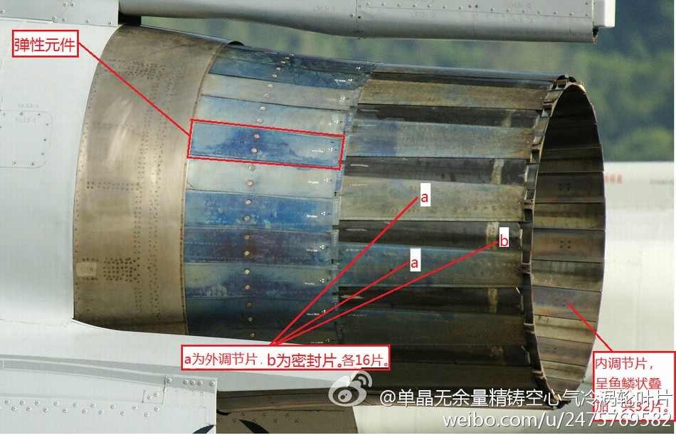
- The segmented afterburner nozzle of the AL-31FN turbofan. The AL-31FN produces 17,857lbs of
- thrust dry and 27,557lbs of thrust in afterburner.

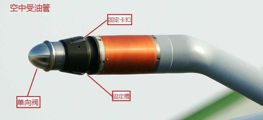
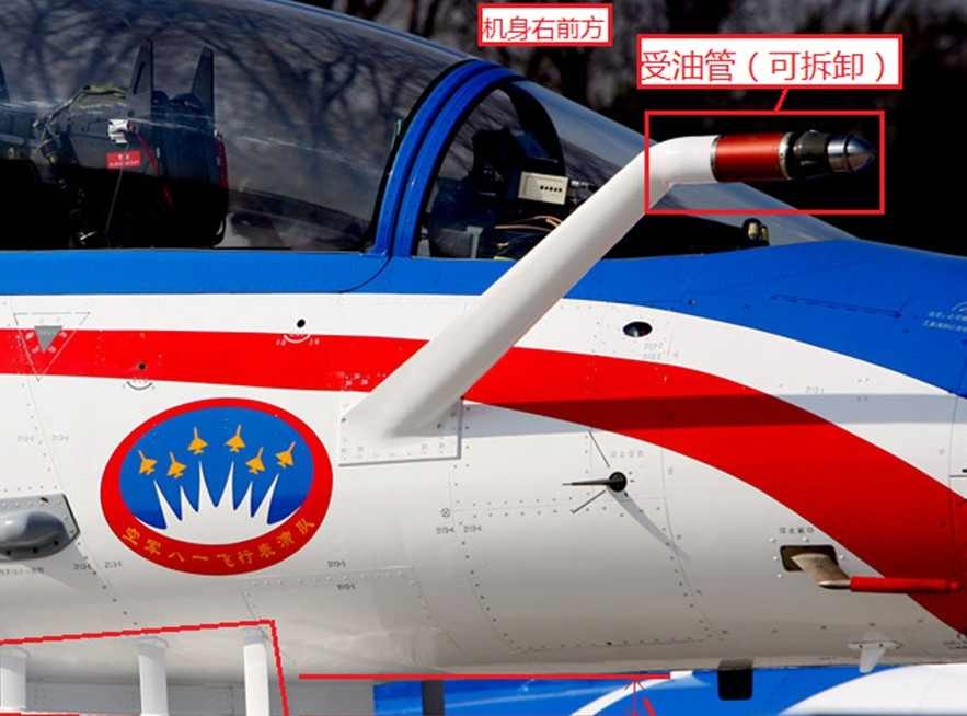
- A close up detail view of the J-10s in-flight refueling probe. The probe itself is fixed but detachable.

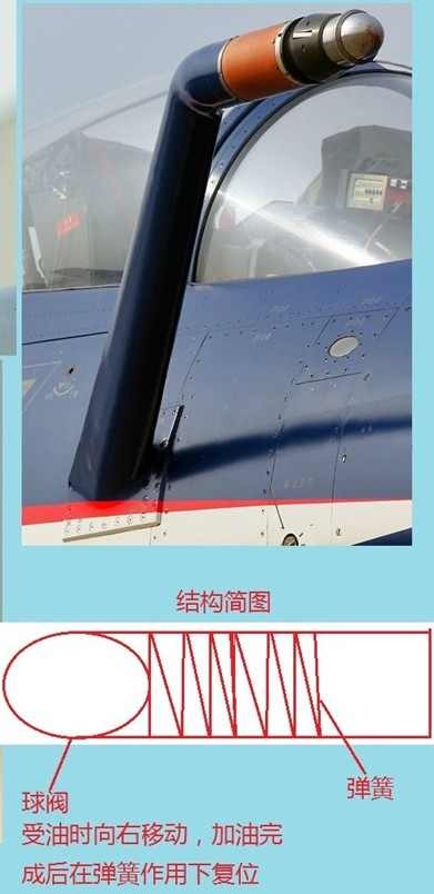
- Another detail view of the J-10’s bolt-on fixed inflight refueling probe. A illumination light for refueling at night is fitted below the windscreen on the starboard side only.

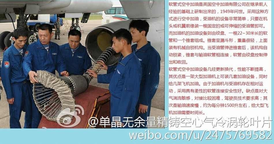
- A closeup of the H-6U tanker’s in-flight refueling hose basket.

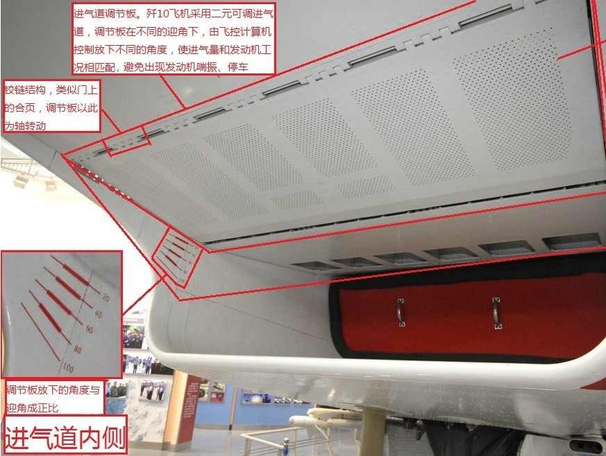
- The ventral engine intake of the J-10. The 2 segmented inlet ramp is perforated to prevent ingestion of
- the stagnant boundary layer. The ramp is designed to slow down incoming air to subsonic speeds before
- the airflow reaches the turbofan engine face. The forward segment of the ramp appears to have a range
- of motion, at the forward hinge, 30 degrees.

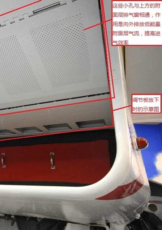
- A closeup of the forward inlet ramp’s perforation. Note the red engine air intake cover.

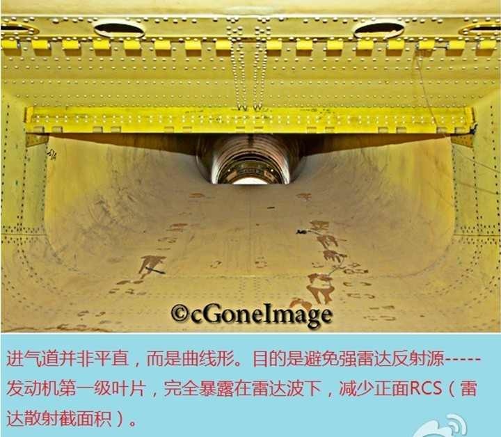
- A “down the throat” look at the ventral engine intake (with the AL-31FN engine removed).

- Upper left: A detail view of the ground refueling receptacle and some interesting detail of the wing/fuselage
- junction. Also detail of the parachute housing in the tail.

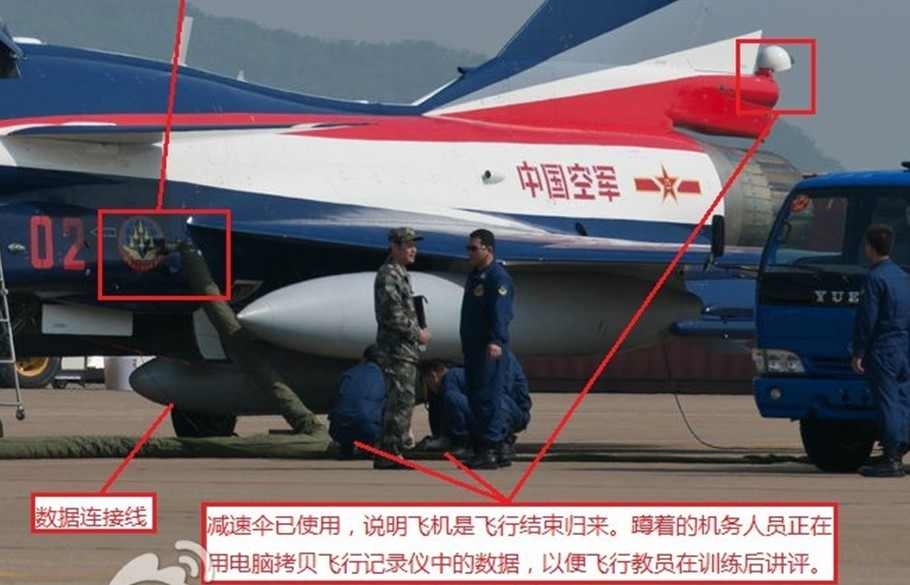
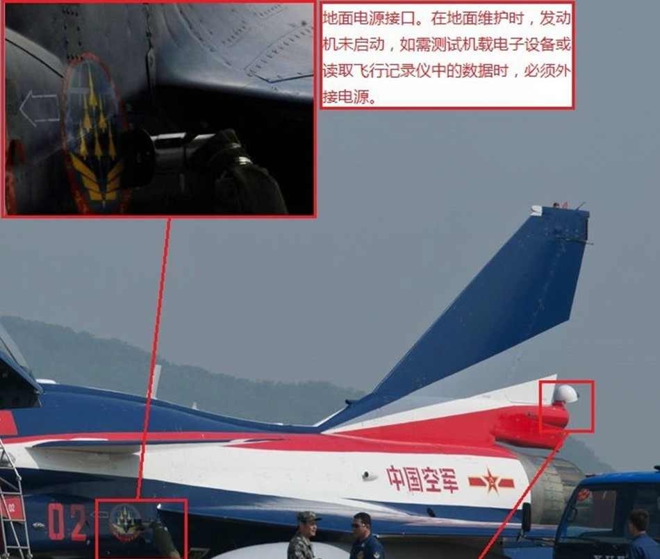
- A look at a few on the ground servicing point of the J-10. The red boxes in the photo highlight the ground
- refueling receptacle and the open parachute container at the tail.

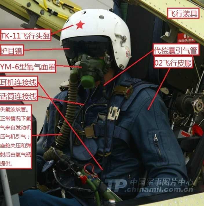
- The standard PLAAF TK-11 helmet with attachment point for a helmet mounted sight receptacle. A
- YM-6 oxygen mask and various other life support equipment for the pilot including oxyygen hose, koch
- fittings, and g-suit.

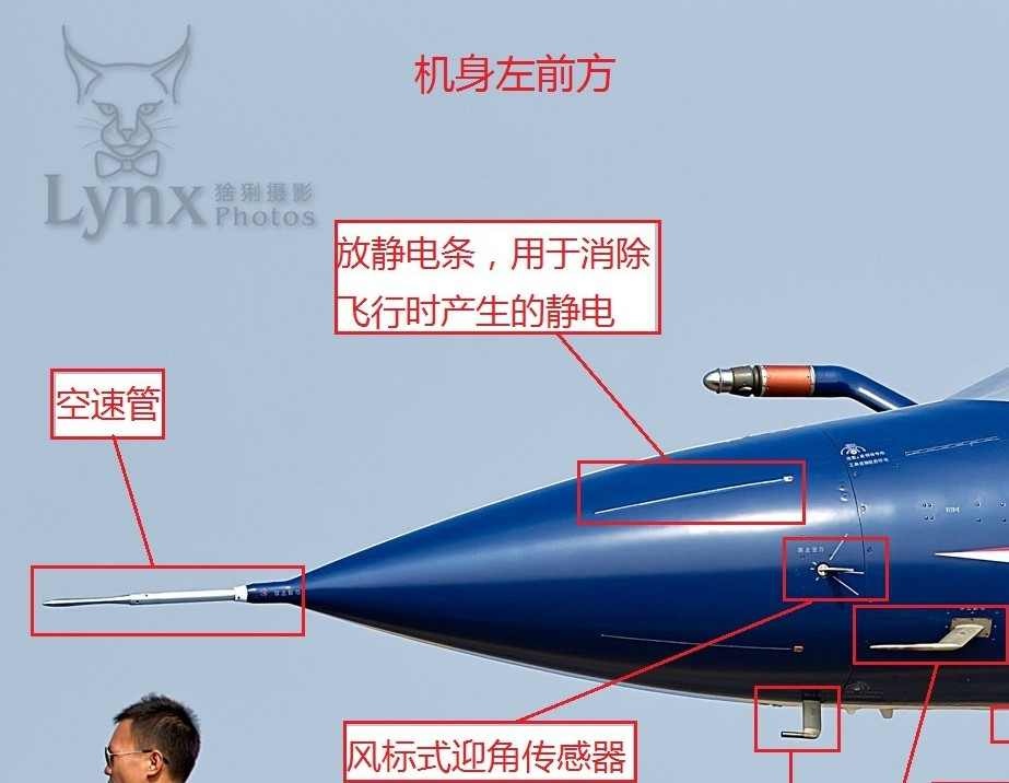
- A look up close at the forward fuselage. The 3 struts above the air intake at the lower left. The ECM
- fairing immediately above in gray. The insignia is that of the August 1st display team. Immediately in
- front and slightly below the AoA probe and the IFR probe illumination light is above. Further forward
- and just below the red cheatline is an air data probe for airspeed indication.

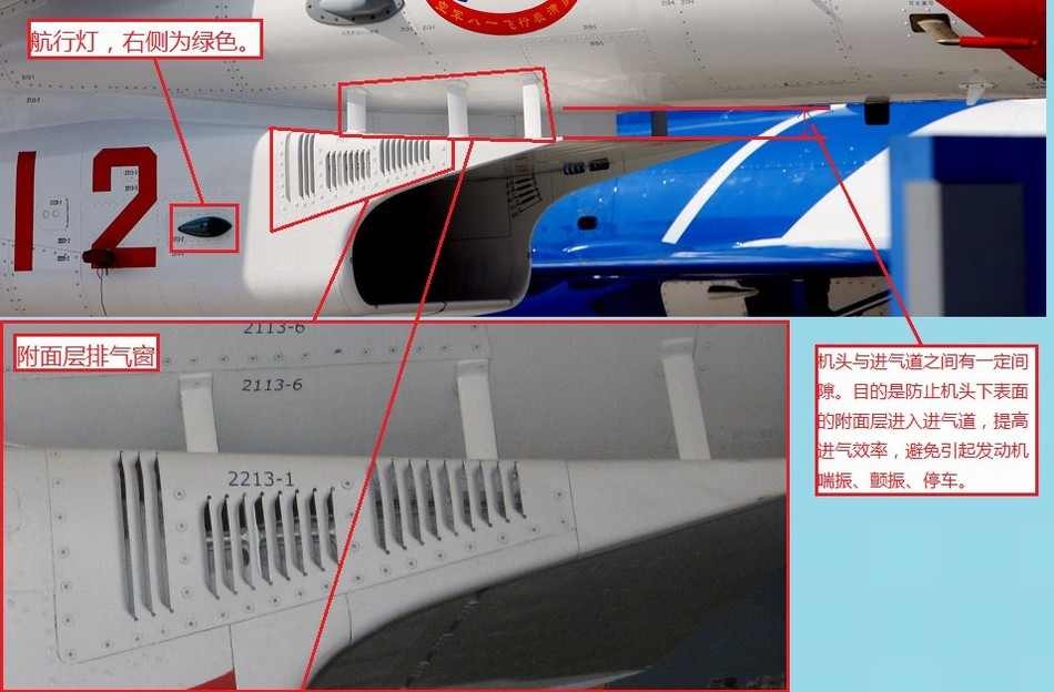
- Top photo is detail of the 3 struts keeping the intake out of the fuselage boundary layer. The vents on the
- side provide exhaust for the boundary layer separated by the intake ramp. Next to digit “12” is a green
- navigation/station keeping light. Also note the numbers on the panels for easier maintenance.


- A close up of the J-10s intake struts. These lower the intake out of the boundary layer and help the fuselage/intake section maintain a form of structural rigidity. Behind the struts is another longitudinally
- mounted separator strut.

- Above the person’s head is the air data probe. The lines on the radome are lightning strike dischargers.
- Between the 2 dischargers is an AoA probe. the the bottom is another probe probably for air pressure
- and aft of the AoA probe is another airdata probe for the pitot static system.

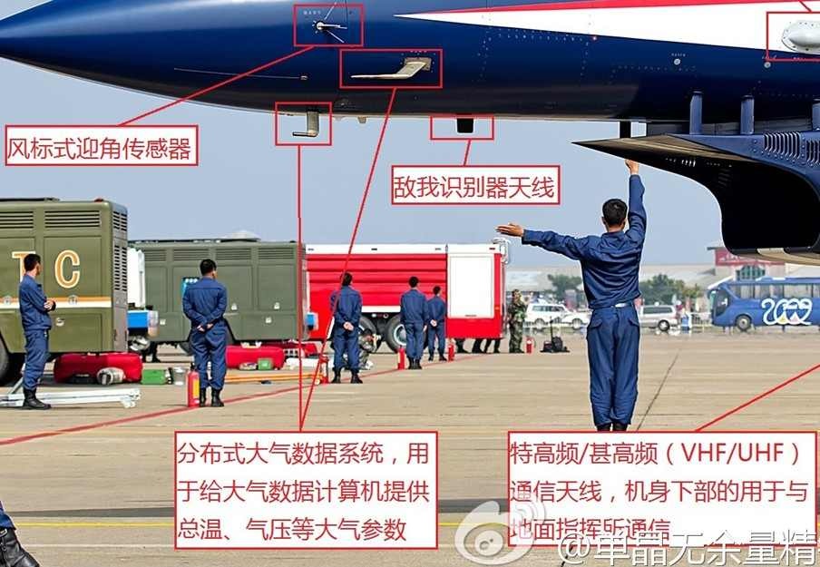
- Other than what’s pointed out in the previous picture, the rectangular antenna is for the UHF/VHF radio.

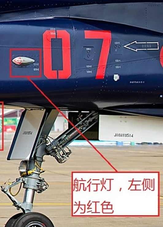
- Forward of the “07” digit is the red navigation/station keeping light. There are various panels around the digits but the arrow points rescue crews to the panel to manually jettison the canopy from the outside. Also visible on the nosegear door is the aircraft construction number (this is an assigned number at the factory) “J10AY0514.” The number is also repeated in the front of the smaller door forward of the nosegear main strut.

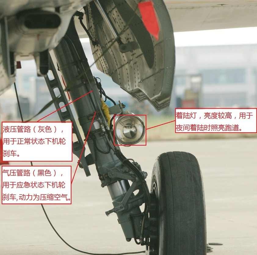
- A detail view of the port side main gear and associated equipment. The landing light and the various
- hydraulic and electrical lines.

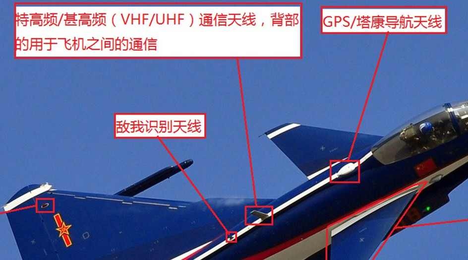
- An in-flight view of the J-10AY from the PLAAF’s August 1st display team. Again immediately behind
- the canopy, GPS, VHF/UHF, and another navigation equipment antenna (maybe a TACAN or LORAN
- type instrument?). On the port side wingtip is the green navigation light. Note the dropped leading edge
- for improved aerodynamic and handling characteristics. Also, note the vapor coming off the leading edge
- indicating some high-g maneuvering.

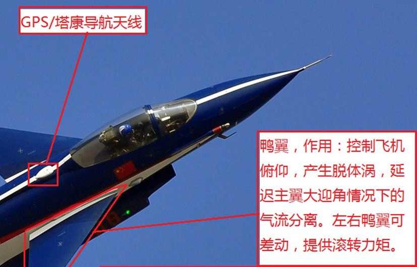
- An in-flight view of the J-10AY detailing the GPS antenna just aft of the canopy. Note the deflection of
- the starboard side canard.

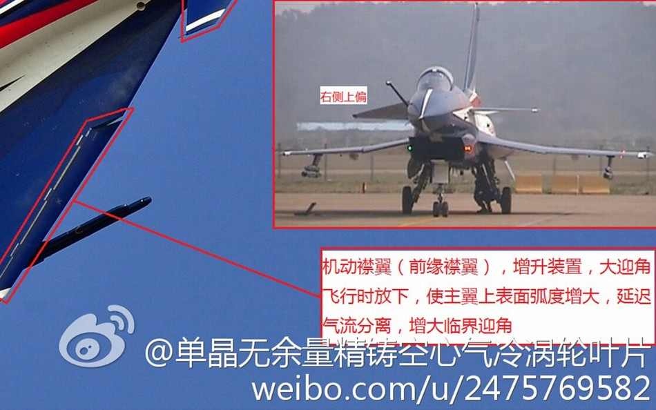
- A comparison of degree of travel of the leading edge slat. The inset view probably shows the closed
- position. The main photo shows the leading edge slat about half deployed.

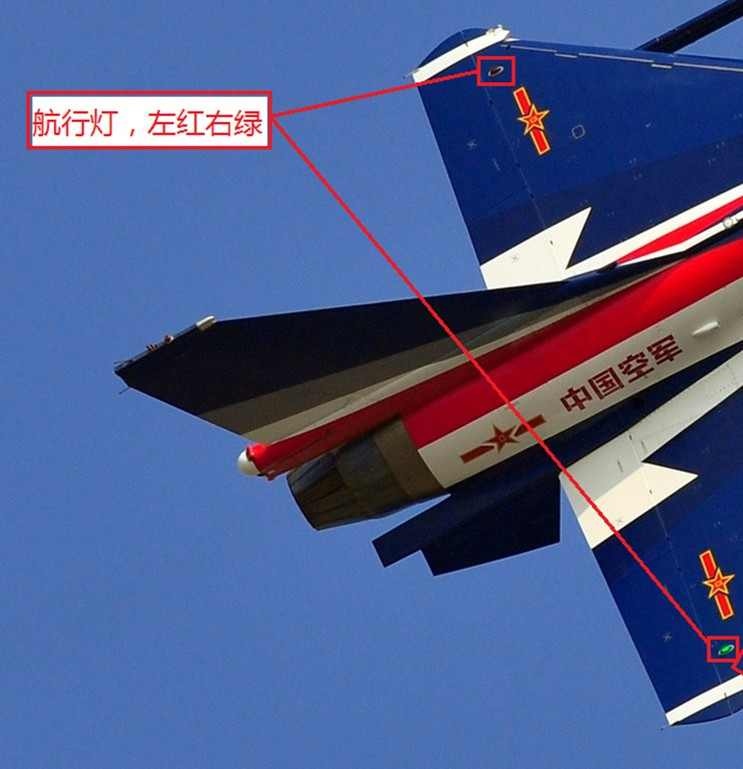
- The same J-10AY, this time the aft fuselage and tail section. Noteworthy here is the strut with the
- ventral fin mounted on it as well as the navigation lights on each wingtip.

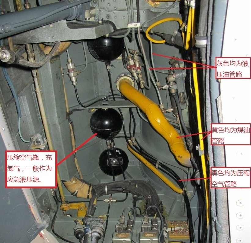
- Detail view on the main landing gear bay showing pneumatic (black) and hydraulic lines (gray). The
- large yellow hose looks like an engine bleed air line.

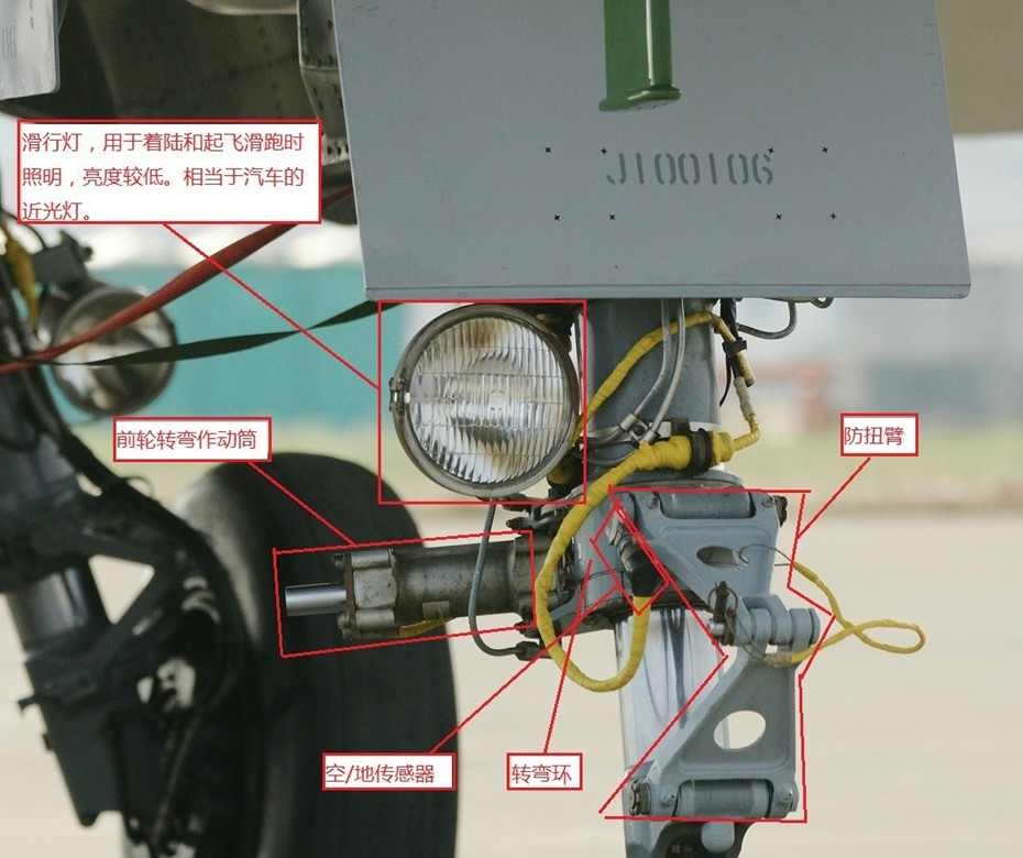
- According to the construction number “J100106″ on the nosegear door of this J-10A is tail number 50556
- it belongs to the 44th Fighter Division, 131st Air Regiment based at Luliang in the Chengdu MR. Also note
- the landing gear light and oleo strut forward. The green antenna just forward of the gear door is for
- navigation equipment.


- J-10 exists in 8 variants:
J-10A: is the first generation version powered by either the WS-10 or AL-31FN turbofan.
J-10S: the combat capable 2-seat version of the A.
J-10AY: a variant unarmed specially developed for the PLAAF’s August 1st display team (similar to the A).
J-10SY: the twin-seat version of the J-10AY.
J-10AH: the single seat variant in service with the PLANAF.
J-10SH: twin seat verision ins service with the PLANAF.
J-10B: an upgraded version of the J-10A.
FC-20: an export version intended for Pakistan.

The J-10B entered full production earlier this year after beginning flight test in 2008.
The J-10B is the next generation version of the J-10 and is the first Chinese fighter equipped with AESA radar and a number of improvements detailed in the picture below:


There are rumors of the existence of another variant of the J-10 called the J-10C but no details are available.
3D view on a defense forum claiming to be the J-10C

Sources:
International Air Power Review Volume 22.
Modern Chinese Warplanes.
J-10 Wikipedia
2013 Chinese Air Force Review.
Post a Comment Blogger Facebook Disqus